
Geometric inspection of machined mechanical parts
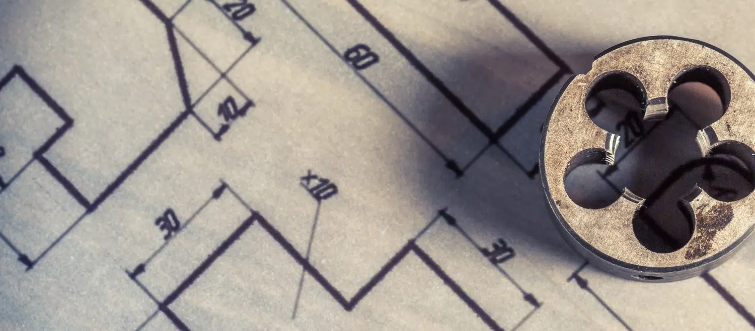
What is control drawing tracing?
Control tracing is used to verify that parts conform to the geometric and dimensional specifications set forth in drawings and specifications. It involves creating a graphic layout, typically on a 1:1 scale, which allows for a visual and geometric comparison of the actual part with the drawing.
Unlike dimensional inspection, which relies on numerical measurements, the creation of a control sketch allows for an analysis of a part’s overall geometry: shapes, angles, alignments, and the relative positions of its components.
Purpose of this audit
- Check the overall consistency of a document
- Inspecting complex shapes that are difficult to measure directly
- Validate specific intersections, radii, slopes, or profiles
- Detect geometric defects before or after machining
- Verify that the actual geometry matches the theoretical geometry.
How Outline Tracing Works
- Transfer the data from the plan (dimensions, angles, radii, axes)
- Create a sketch on a surface (paper, marble, drafting table, or digital surface)
- Transfer the actual geometry of the part to this sketch
- Compare the two paths visually and geometrically
When is control drawing tracing used?
At WIPELEC, control drawing tracing is primarily used for one-off parts or small production runs, as well as for the manufacture of complex or custom-made parts.
This method provides an accurate overview of the part, allows for the immediate identification of geometric defects, adapts perfectly to complex shapes, and serves as a highly effective educational tool for understanding and mastering part geometry.
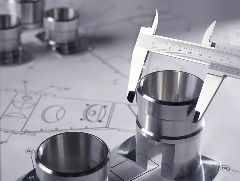
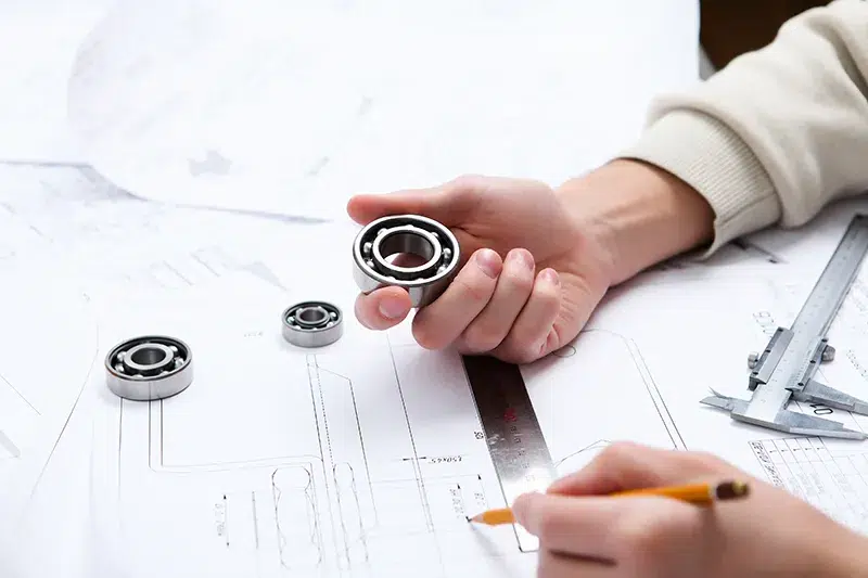
Learn more about control drawing tracing
Do you have questions about the layout drawing for metal parts? Find answers to the most frequently asked questions here!
What defects can be detected through geometric inspection?
Geometric inspection can be used to detect, among other things:
- Flatness defects or deformation in thin parts
- Deviations from parallelism or perpendicularity
- Deviations in profiles, radii, or contours
- Misalignment between cutouts, drill holes, or functional areas
These defects can affect the assembly, precision, or final performance of the part. Identifying them early on helps prevent non-conformities and costly rework.
Is geometric inspection essential for all precision parts?
Not all parts require the same level of inspection, but dimensional inspection becomes essential when the part’s function is critical.
It is particularly recommended for:
- Parts with tight tolerances
- Components designed for demanding technical applications
- Parts produced using microfabrication processes
Even for parts that appear simple, proper geometric inspection ensures quality and repeatability.
Is geometric inspection suitable for one-off and custom-made parts?
Geometric inspection is particularly well-suited for one-off parts, prototypes, or small production runs. In these cases, manual marking and inspection drawings offer great flexibility and excellent clarity. They allow the inspection process to be tailored to each individual part without the need for heavy or automated equipment. This is an ideal approach for custom-made or high-value-added manufacturing.
What is a control drawing?
A control drawing is a detailed graphical representation of a part used as a reference for geometric inspection. It provides a precise visualization of the contours, axes, profiles, functional surfaces, and critical areas to be inspected.
In the context of chemical etching,electroforming, andprecision machining, a technical drawing makes it easier to understand complex geometric relationships and tight tolerances, where simply reading the blueprint may not be sufficient.